Sauer Danfoss Hydraulic Pump Load Sensing Control Working Principle Load Sensing (LS) Control

The LS control adjusts the output flow of the oil pump to match the system demand. The LS controls the pressure drop sensing system flow demand through an external control valve (ECV). As the ECV opens and closes, the pressure drop across the valve changes accordingly. When turned on, the pressure drop decreases. When closed, the pressure drop increases.
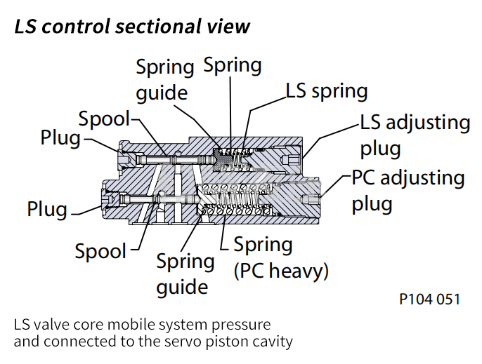
The LS control increases or decreases the pump flow until the pressure drop equals the LS setpoint. The LS setting is preset by the adjusting plug (7) and the spring (8).
The LS control contains two spool valves that connect the servo piston chamber to the pump housing or system pressure. As mentioned above, the PC spool (6) of the sauer danfoss hydraulic oil pump realizes the pressure compensation function of the control. The LS spool (9) implements the load sensing function. The PC control function takes precedence over the LS control function. Through the internal oil passage, the system pressure (external control valve inlet pressure) is led to the non-spring chamber side of the LS spool. At the same time, the outlet pressure of the external control valve is led to the side of the spring cavity of the LS spool through the X port. This configuration allows the LS spool to move between the spring setting and the differential pressure between the system pressure and the LS signal pressure. Finally, the pressure difference between the two ends is equal to the LS spring setting (LS set value).

The sauer danfoss hydraulic oil pump provides maximum flow to the hydraulic system as the swash plate is pre-biased by springs to the maximum swivel angle. When the flow supply exceeds demand, the differential pressure developed across the ECV (external control valve) is sufficient to overcome the LS spring force and move the LS spool to the left to connect the system pressure to the servo piston chamber. The pump responds by reducing flow output until the differential pressure across the ECV equals the LS setpoint. When the flow supply is lower than the demand, the pressure difference formed by the two ends of the ECV is less than the LS set value, and the LS spool moves to the right position, thereby making the servo piston cavity and the pump housing
connected. The pump reverts to increasing flow output until the increment through the ECV equals the LS setpoint.
When the external control valve is in neutral, it connects the LS signal line to the drain port. In the absence of force on the non-spring end of the LS spool, the Sauer Danfoss hydraulic oil pump can adjust itself to any position to maintain the system pressure at the LS setting. The pump is now in standby mode. Due to the tandem arrangement of the LS and PC spools, the PC control overrides the LS control. As long as the system pressure reaches the PC setting value, the PC spool will move to block the communication between the LS spool and the servo piston chamber, directly connecting the servo piston chamber with the system pressure to minimize the pump displacement.